- Home
- Parts by Type
- Parts by Bike
-
Installation Instructions and Videos
-
V-Strom Parts Instructions
>
- Mirror Extender Instructions
- Fork Brace Instructions
- Footpeg and Control Lowering Instructions
- Gear Shift Relocation Instructions
- Bolt-on Kickstand Foot Instructions
- Raising and Lowering Links >
- Shelves and GPS Mounts >
- DL1000 Rear Wheel Spacer Instructions
- Vee2 Saddlebag Guard
- Fender Riser 2014+ DL1000
- 2012+ DL650Fender Risers
- Retrieving Missing Parts from the Cowling
- Auxiliary Lighting >
- DL800 GIVI Crash Bars
- General Electrical and Lighting >
- Brake Lines >
- Kawasaki Versys X300 >
- Yamaha Parts Instructions >
-
V-Strom Parts Instructions
>
- Shorter/Taller Riders
- Favorite Projects
- Adventure Motorcycling Links
- Frequently Asked Questions
- Contact Us
- Photos
- Specials and Promotions
12 O'Clock Labs Running Light Adapters
Installation Instructions
Your 12 O'Clock Labs Running Light Adapters (RLA) come with written instructions. These instructions are intended to cover two types of RLA and a variety of motorcycles. Specific instructions for the V-Strom are included in the instructions supplied. The instructions here are intended as a V-Strom specific supplement for the 12 O'Clock Lab instructions.
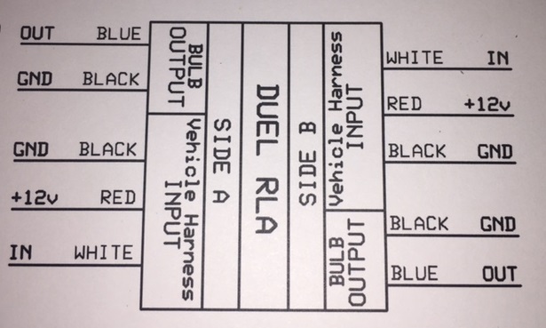
The instructions include a diagram of a Dual Output RLA. The dual output RLA has both left and right sides built into a single module.
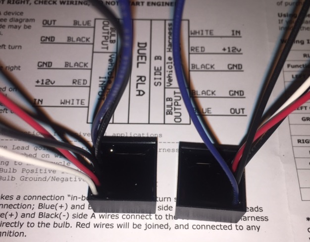
However, instead your kit includes two single modules. The only difference is that the left and right sides are in separate pieces. Imagine the diagram above with the center section removed.
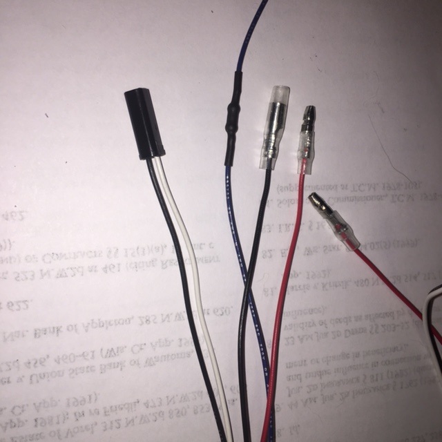
If you orient the two single modules as in the picture below the wiring matches exactly.
If you orient the two single modules as in the picture below the wiring matches exactly.
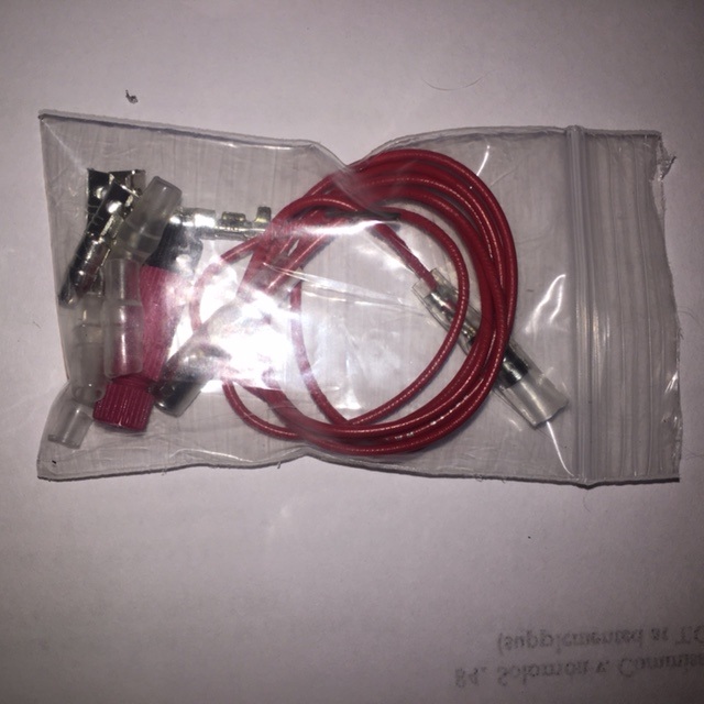
Now take the red wire out of the package.
Connect this red wire from the package to the red wires coming from each RLA.
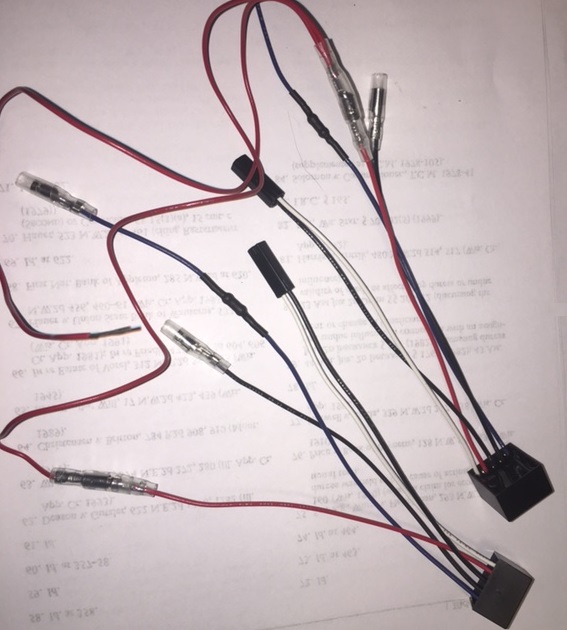
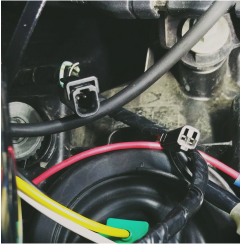
The black and white leads coming from the RLAs have a black electrical connector matching the connector to your turn signals. Unplug your turn signal from the wiring harness and plug this connector into the wiring harness.
So the red wire, and the white and black wires with connector have been addressed, now it's time for the the blue and black wires.
It turns out that 99% of these kit are sold to people installing aftermarket turn signals on other motorcycles. So instead of a connector that would simply connect the blue and black wires to the turn signal, the kit includes the most common connectors suitable for after market turn signals.
So for V-Stroms, snip the stock connector off and install the new crimp connectors corresponding to the appropriate blue or black wire from the RLA.
The blue RLA wire goes to the turn signal positive and the black to the turn signal negative.
In summary:
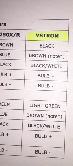
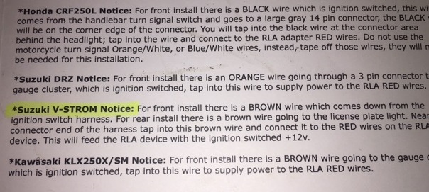
RLA red wires - connected together and then to a switched power source.
Black and White wires with connector - connect to wiring harness
Black and Blue wires - connect to turn signals using new connectors
